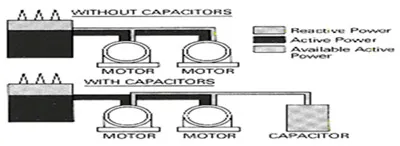
Power factor is the relationship between working (active) power and total power
consumed (apparent power). Essentially, power factor is a measurement of how effectively
electrical power is being used. The higher the power factor, the more effectively electrical power
is being used.
A distribution system's operating power is composed of two parts: Active (working) power and
reactive (non-working magnetizing) power. The ACTIVE power performs the useful work - the REACTIVE
power does not. It's only function is to develop magnetic fields required by inductive devices.
| Initial PF Target PF | ||||||||||
| 0.90 | 0.91 | 0.92 | 0.93 | 0.94 | 0.95 | 0.96 | 0.97 | 0.98 | 0.99 | |
| 0.4 | 1.807 | 1.836 | 1.865 | 1.896 | 1.928 | 1.963 | 2.000 | 0.97 | 2.041 | 1.910 |
| 0.42 | 1.676 | 1.705 | 1.735 | 1.766 | 1.798 | 1.832 | 1.749 | 1.790 | 1.680 | 1.577 |
| 0.44 | 1.557 | 1.585 | 1.615 | 1.646 | 1.678 | 1.712 | 1.639 | 1.481 | 1.392 | 1.308 |
| 0.46 | 1.446 | 1.475 | 1.504 | 1.535 | 1.567 | 1.602 | 1.536 | 1.229 | 1.154 | 1.083 |
| 0.48 | 1.343 | 1.372 | 1.402 | 1.432 | 1.465 | 1.499 | 1.440 | 1.015 | 0.950 | 0.888 |
| 0.5 | 1.248 | 1.276 | 1.306 | 1.337 | 1.369 | 1.403 | 1.351 | 0.828 | 0.770 | 0.713 |
| 0.52 | 1.158 | 1.187 | 1.217 | 1.247 | 1.280 | 1.314 | 1.267 | 0.658 | 0.631 | 0.605 |
| 0.54 | 1.074 | 1.103 | 1.133 | 1.163 | 1.196 | 1.230 | 1.188 | 0.552 | 0.499 | 0.447 |
| 0.56 | 0.995 | 1.024 | 1.053 | 1.084 | 1.116 | 1.151 | 1.113 | 0.395 | 0.369 | 0.343 |
| 0.58 | 0.920 | 0.949 | 0.979 | 1.009 | 1.042 | 1.076 | 1.042 | 0.316 | 0.289 | 0.262 |
| 0.6 | 0.849 | 0.878 | 0.907 | 0.938 | 0.970 | 1.005 | 0.974 | 0.234 | 0.253 | 0.175 |
| 0.62 | 0.781 | 0.810 | 0.839 | 0.870 | 0.903 | 0.937 | 0.909 | 0.145 | 0.112 | 0.078 |
| 0.64 | 0.716 | 0.745 | 0.775 | 0.805 | 0.838 | 0.872 | 0.847 | 0.98 | 2.088 | 1.958 |
| 0.66 | 0.654 | 0.683 | 0.712 | 0.743 | 0.775 | 0.810 | 0.787 | 1.838 | 1.727 | 1.625 |
| 0.68 | 0.594 | 0.623 | 0.652 | 0.683 | 0.715 | 0.750 | 0.729 | 1.529 | 1.440 | 1.356 |
| 0.7 | 0.536 | 0.565 | 0.594 | 0.625 | 0.657 | 0.692 | 0.672 | 1.276 | 1.201 | 1.130 |
| 0.72 | 0.480 | 0.508 | 0.538 | 0.569 | 0.061 | 0.635 | 0.617 | 1.062 | 0.998 | 0.935 |
| 0.74 | 0.425 | 0.453 | 0.483 | 0.514 | 0.546 | 0.580 | 0.590 | 0.875 | 0.817 | 0.761 |
| 0.75 | 0.380 | 0.426 | 0.456 | 0.487 | 0.519 | 0.553 | 0.706 | 0.679 | 0.652 | 0.706 |
| 0.76 | 0.371 | 0.400 | 0.429 | 0.460 | 0.492 | 0.526 | 0.563 | 0.699 | 0.547 | 0.495 |
| 0.78 | 0.318 | 0.347 | 0.376 | 0.407 | 0.439 | 0.474 | 0.511 | 0.443 | 0.417 | 0.390 |
| 0.8 | 0.266 | 0.294 | 0.324 | 0.355 | 0.387 | 0.421 | 0.458 | 0.364 | 0.337 | 0.309 |
| 0.82 | 0.214 | 0.242 | 0.272 | 0.303 | 0.335 | 0.369 | 0.406 | 0.281 | 0.313 | 0.223 |
| 0.84 | 0.162 | 0.190 | 0.220 | 0.251 | 0.283 | 0.317 | 0.354 | 0.192 | 0.160 | 0.126 |
| 0.85 | 0.135 | 0.164 | 0.194 | 0.225 | 0.257 | 0.291 | 0.328 | 0.99 | 2.149 | 2.018 |
| 0.86 | 0.109 | 0.138 | 0.167 | 0.198 | 0.230 | 0.265 | 0.302 | 1.898 | 1.788 | 1.685 |
| 0.87 | 0.082 | 0.111 | 0.141 | 0.172 | 0.204 | 0.238 | 0.275 | 1.590 | 1.500 | 1.416 |
| 0.88 | 0.055 | 0.084 | 0.114 | 0.145 | 0.177 | 0.211 | 0.248 | 1.337 | 1.262 | 1.191 |
| 0.89 | 0.028 | 0.057 | 0.086 | 0.117 | 0.149 | 0.184 | 0.221 | 1.123 | 1.058 | 0.996 |
| 0.9 | 0.029 | 0.058 | 0.089 | 0.121 | 0.156 | 0.193 | 0.936 | 0.878 | 0.821 | |
| 0.91 | 0.030 | 0.060 | 0.093 | 0.127 | 0.164 | 0.205 | 0.766 | 0.739 | 0.713 | |
| 0.92 | 0.031 | 0.063 | 0.097 | 0.134 | 0.660 | 0.608 | 0.556 | |||
| 0.93 | 0.032 | 0.067 | 0.104 | 0.503 | 0.477 | 0.451 | ||||
| 0.94 | 0.034 | 0.071 | 0.424 | 0.397 | 0.370 | |||||
| 0.95 | 0.037 | 0.342 | 0.313 | 0.284 | ||||||
How Power Factor Correction Capacitors Solve the Problem of Low Power Factor.
Low power factor is a problem that can be solved by adding power factor correction capacitors to the plant distribution system. Correction capacitors work as reactive current generators “providing” needed reactive power (kvar) into the power supply. By supplying their own source of reactive power, the industrial user frees the utility from having to supply it, therefore, the total amount of apparent power supplied by the utility will be less.

Power factor correction capacitors reduce the total current drawn from the distribution system and subsequently increase system capacity by raising the power factor level.
Power factor correction capacitors are rated in electrical units called “Vars”. One Var is equivalent to one volt-ampere of reactive power. Vars, then, are units of measurement for indicating just how much reactive power the capacitor will supply. As reactive power is usually measured in the thousands of Vars, the letter “k” (abbreviation for kilo”, meaning thousands) precedes the Var creating the more familiar “kVAR” term.The capacitor kVAR rating, then, shows how much reactive power the capacitor will supply. Each unit of the capacitor’s kVAR will decrease the inductive reactive power demand (magnetizing demand) by the same amount
EXAMPLE :
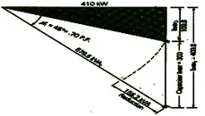
A low voltage network requires 410 kW active powers at full load, and the power factor is measured to be .70. Therefore, the system’s full load consumption of apparent power is 579.5 kVA. If 300 kvar of capacitive reactive power is installed, the power factor will rise to .96 and the kVA demand will be reduced from 579.5 to 424.3 kVA.

Causes Of Low Power Factor
Disadvantages Of Low Power Factor
The Power Factor plays an important role in A.C. Circuit since power consumed
depends upon this factor.
P = VL x IL x COS(Ф) (For Single Phase)
IL = P/ VL COS(Ø)
P = 1.73 x VL x IL x COS(Ø) (For Three Phase)
IL = P/ 1.73 x VL x COS(Ø)
It is clear from above that for fixed power & voltage the load current is inversely proportional
to the power factor. Lower the power factor, higher the load current & vice-versa.
The above discussion indicates that the low power factor is an objective feature
in the supply system.
The Principle Of Power Factor Compensation
While the ideal Power Factor (PF) is Unity or 1, most Industrial loads have a PF lower than 1.
Moreover, this lower PF is usually Inductive, arising out of the windings of Transformers, Motors,
etc. These loads consume KVARs (the Watt less component) from the supply line.
The principle of PF Compensation is to supply these KVARs via a capacitor located close to the
load, reducing the current drawn from the supply line.
The low lagging power factor is mainly due to the fact that most of the power
load is inductive in nature & therefore, take lagging current. In order to improve the power
factor, some drive taking leading power factor should be a capacitor. The capacitor draws a
leading current & partly neutralizes the lagging reactive power of load current. This raises the
power factor of the load.
The devices of Power Factor improvement are as below
Power factor Correction is achieved now a days by installing power capacitors .
Under fixed load conditions it is possible to put power capacitors in the system which will
compensate completely for the wattles component and power factor can be improved to its maximum
value. This obviously will not be an exact compensation for loads which are varying in value.
Power factor can be controlled manually or by automatic control systems.
In manual control the operator has to go on making adjustment all the time, which is very tricky
and human error cannot be ruled out.
In automatic control, power factor control relay keeps on sensing the power factor all the time
and gives suitable signals to contactors connected to it to energize required capacitors.
Power capacitors have been used in many & wide ways in industry from last 40-50
years but its continuous use is often limited by apparent lack of practical application
information.
The various applications of capacitors are capacitors for power factor improvement, Series
Capacitors in power supply system, surge protection capacitors, Voltage divider Capacitors, Energy
Storage Capacitors, Motor Start/Run Capacitors, Fluorescent lighting capacitors, harmonic filter
capacitors ,water cooled capacitors etc.