
PRODUCT RANGE
Rated output: 500 KVAR to 5000 KVAR
Rated Voltage: 1 KV to 33 KV
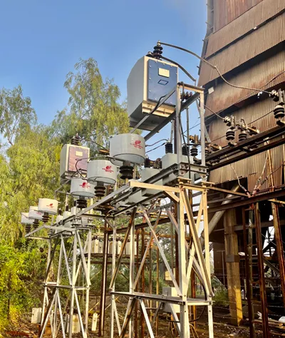
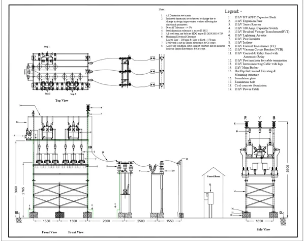
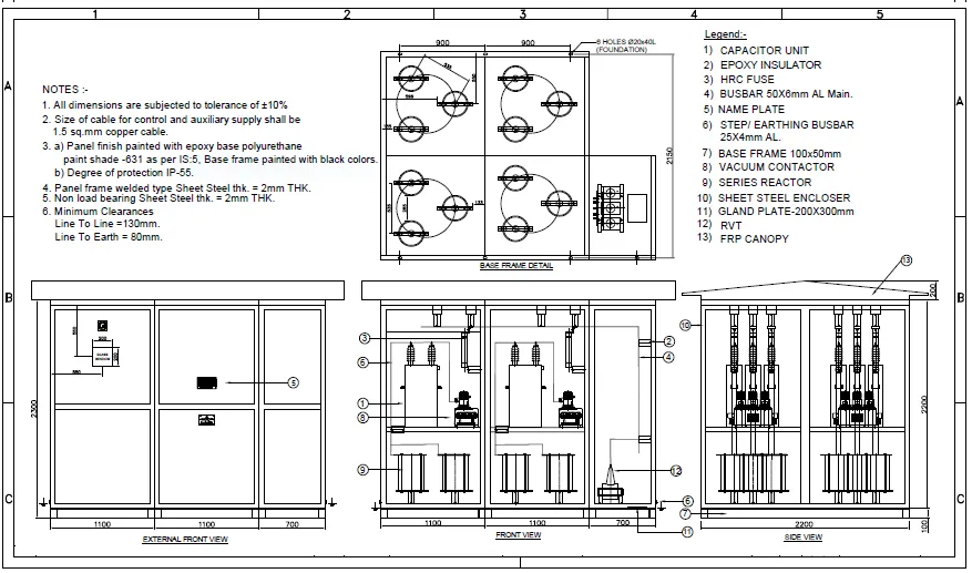
MV/HV APFC capacitor metal enclosed panel is normally used where system having less space with very high fluctuating loads at MV/HV side.
For optimum utilization of available power, the reactive power consumption should be reduced or
nullified i.e. power factor should be unity, hence, most of the Power Distribution companies
have policy to penalize the industrial and commercial consumers for not maintaining power factor
in Leading as well as in Lagging.
However, due to reactive power drawn by capacitive or inductive load in the consumer premises
the power factor is either lagging or leading, thus to maintain it within limit i.e. for
compensating or supplying required KVAR, the capacitors (in case of lagging PF) or reactors ( in
case of leading PF) are connected across the system.
For stable load the fixed KVAR compensation is
required, while for variable load the KVAR requirement also changes as per the load duration
cycle, thus in such case the Automatic Power Factor Control Panel is installed.
Introduction :
A High Voltage APFC (Automatic Power Factor Correction) Capacitor Panel is an electrical system used to improve the power factor of an electrical distribution network. Power factor is a measure of how effectively electrical power is being used. A low power factor indicates that a significant portion of the electrical power is reactive power, which doesn't perform useful work but still requires energy to be generated and transmitted
APFC Capacitor Panels are used to mitigate low power factor issues in industrial and commercial settings. These panels are designed to automatically control and adjust the connection of capacitors to the electrical system in order to improve the power factor. Capacitors are electrical devices that store and release electrical energy in the form of reactive power. By adding capacitors to the system, the overall power factor can be improved, which leads to more efficient use of electrical power, reduced energy losses, and increased system capacity
Major Component of HT APFC Capacitor Panel :
The Details of above component used in our HT APFC Capacitor Panel
These are the core components of the panel. They are connected in parallel to the system and provide reactive power to offset the reactive power demands of inductive loads (like motors). Capacitors can be switched on or off as needed to maintain an optimal power factor.
The Reactors are used in both way one is for Harmonics Filtration and other is for inrush current limiting purpose. These reactor are either iron core type or air core type.
These are the devices responsible for physically connecting and disconnecting the capacitors to the electrical system. They need to handle high voltages and currents safely.
The controller is the brain of the APFC panel. It monitors the system's power factor and voltage levels and makes decisions about when and how many capacitors to connect or disconnect. Modern controllers use microprocessors and programming to automate these decisions.
Sensors are used to measure key electrical parameters like voltage, current, power factor, and frequency. These measurements are fed to the controller for analysis and decision-making
High Voltage APFC panels should be equipped with protective devices like circuit breakers, fuses, and overcurrent relays to prevent equipment damage and ensure safety
In advanced systems, the APFC panel might be equipped with communication capabilities to connect with a central control system or to enable remote monitoring and control
Installing a High Voltage APFC Capacitor Panel can have several benefits, including reduced energy bills, increased system capacity, and improved overall system efficiency. However, designing and implementing such systems require careful consideration of the electrical load, power factor characteristics, and safety requirements. It's important to work with experienced electrical engineers and professionals when designing and installing these panels
These banks consist of:


